-
Highlight
heller reflow oven
,lead free reflow ove
-
BrandCNSMT
-
MODELCN089
-
Weight670KG
-
Lead TimeIN Stork
-
PackingWOODENBOX
-
POWER3-phase 5-wire 380V
-
PCB WIDTH50-350MM
-
PAYMENT TERMT/T, Paypal, Westernunion Are All Allowed
-
Place of Originchina
-
Brand NameCNSMT
-
CertificationCE
-
Model NumberCN089
-
Minimum Order Quantity1
-
Pricenegotiation
-
Packaging Detailswoodenbox
-
Delivery Time5-7 work days
-
Payment TermsT/T, Western Union
-
Supply Ability10pcs/day
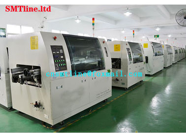
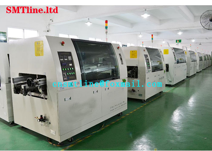
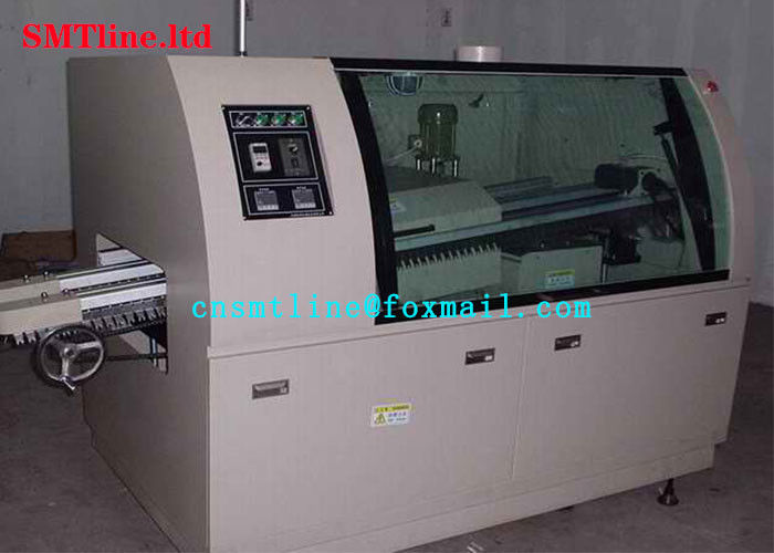
CN089 SMT Wave Soldering Machine Lead Free 670KG Weight With PID Control
CNSMT 10 years production WAVE SOLDERING MACHINE after dip component
Feature
| P C Broad width | Board width | Max200mm |
| PCB conveyor height | PCB transportation height | 700±20mm |
| PCB conveyor speed | PCB transport speed | 0-1.8m/min |
| Preheating length | Preheat zone length | 400mm |
| Preheating Temperatures | Preheat zone temperature | Room temperature ~ 180 degrees |
| Suitable solder type | Suitable solder type | Lead-free solder, ordinary solder |
| Preheating capacity | Preheat power | 2KW |
| Wave solder pot | Wave soldering furnace power | 6KW |
| Solder volume | Solder tin capacity | Lead-free 120KG |
| Solder temperature | Tin furnace temperature | Room temperature ~300 degrees |
| Temperature control | Temperature control method | PID control, SSR drive |
| Flux storage tank | Flux capacity | Max5.2L |
| Power requirements | power supply | 3-phase or single-phase 220VAC |
| Power for heating up | Starting power | 8KW |
| Power for operation | Normal operating power | 2.0KW-2.5KW |
| Air supply | Gas source | 4-7kg/cm2 12.5L/min |
| Control fashion | Whole control method | PLC+ Meter/PLC+Touch Screen |
| Weight | weight | Max 350kg |
| Dimensions | Dimensions | L2200xW1100xH1500 |
Application
Wave soldering machine basic operating procedures
(Reference)
B1 wave soldering machine basic operating procedures
B1.1 Preparation
a. Check whether the wave soldering machine is equipped with ventilation equipment is good;
b. Check the wave soldering machine timing switch is good;
c. Check if the tin bath temperature indicator is normal.
Method: Adjust the temperature indicator up and down, and then use a thermometer to measure the temperature of the tin bath surface 10-15 mm, and determine whether the temperature changes with it:
d. Check whether the preheater system is normal.
Method: Turn on the pre-heater switch and check if it is warm and the temperature is normal.
e. Check the operation of the cutting knife.
Method: Adjust the height of the blade according to the thickness of the printed circuit board and the length of the remaining component lead. Then tighten and stabilize the blade holder, start the visual inspection of the rotation of the blade, and finally check the failure of the insurance device;
f. Check whether the supply of compressed air to the flux container is normal;
Method: Pour the flux, adjust the inlet valve, start the flux foam, use the sample board to adjust the foam to 1/2 of the plate thickness, and then tighten the IOP valve until the formal operation. Then move this valve, just open the air intake switch;
Operating rules
a. The wave soldering machine must send 1 to 2 trained professional staff for operation and management, and be able to perform general maintenance;
b. Before starting the machine, the operator must wear roving gloves and wipe the equipment clean with cotton yarn, and inject proper amount of lubricant into the oil injection hole;
c. Operators should wear rubber anti-corrosion gloves to remove waste and dirt around tin tanks and flux tanks;
d, no flammable articles such as gasoline, alcohol, cotton yarn, etc. shall be stored around the equipment in the operating room;
e. When the welder is running, the operator must wear a respirator and wear a heat-resistant flame-resistant glove.
f. Non-workers shall not enter the wave soldering operation room casually;
g. smoking in the workplace is not allowed to eat food;
h. Wear work caps, shoes, and work clothes when performing the insertion work.
B2 single machine wave soldering operation
B2.1 Open the ventilation switch.
B2.2 boot
a. Turn on the power;
b. Switch on the solder bath heater;
c. Open the foam switch air intake switch;
d. When the solder temperature reaches the specified data, check the tin level. If the tin level is too low, add solder in time;
e. Turn on the wave solder gas pump switch and adjust the tinning depth with a special fixture equipped with a printed board;
f. Remove residual oxide from the tin surface and add anti-oxidant after the tin surface is clean:
g. Check the flux, if the liquid level is too low, add appropriate amount of flux;
h. Check to adjust the flux density to meet the requirements;
i. Check whether the flux foam layer is good;
j. Turn on the preheater temperature switch and adjust to the desired temperature position; k. Adjust the angle of the drive rail;
l. Turn on the conveyor switch and adjust the speed to the required value;
m. Open the cooling fan;
n. The welding fixture into the guide;
o. The printed board is loaded into the fixture, the board is tightly clamped around the fixture slot, the force is moderate, and then the fixture is placed at the beginning of the transfer rail;
p. Prior to the welding operation, the tilted components shall be straightened by a person, and the correct components shall be verified;


