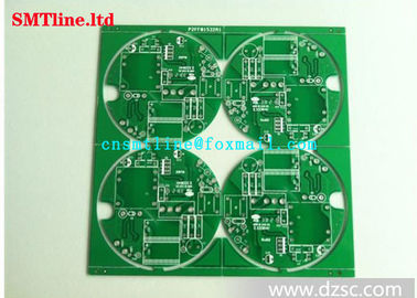
Electronic Assembly SMD LED PCB Board For Led Round Bulb CE Certification
-
Highlight
smd led circuit board
,smt electronic components
-
BrandCNSMT
-
MODELElectronic Printed Circuit Board
-
Weight0.5KG
-
Lead TimeIN Stork
-
PackingBOX
-
CONditionWorking
-
POWER110V/220
-
PAYMENT TERMT/T, Paypal, Westernunion Are All Allowed
-
Place of Originchina
-
Brand Namecnsmt
-
CertificationCE
-
Model NumberSMD LED PCB Board
-
Minimum Order Quantity1
-
Pricenegotiation
-
Packaging Detailswoodenbox
-
Delivery Time5-7 work days
-
Payment TermsT/T, Western Union
-
Supply Ability10pcs/day
Electronic Assembly SMD LED PCB Board For Led Round Bulb CE Certification

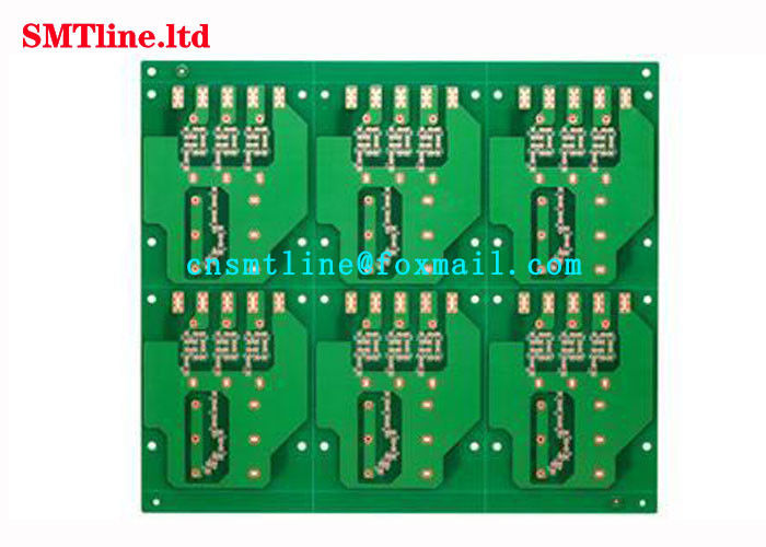
cnsmt design circuit, Assembling pcb board electronic assembly pcb led round bulb pcb board
Quick Detail
| Product Name: | SMD LED PCB Board |
| Used for: | SMT FACTORY Electronic Circuit Board |
| Warranty: | 1 Year |
| Shipment | by air |
| Delivery Time: | 1-2Days |
| Our Main Market | Whole of the world |
Design step editing
Layout design
In the PCB, special components refer to the key components in the high-frequency part, the core components in the circuit, the components that are subject to interference, the components with high voltage, the components that generate large amounts of heat, and some heterogeneity components. The location of these special components requires careful analysis, with the requirements for layout and circuit functionality and production requirements. Improper placement of them may cause circuit compatibility issues, signal integrity issues, and lead to PCB design failures.
In the design of how to place special components, first consider the size of the PCB. Fast Tesco pointed out that when the pcb size is too large, the printing lines are long, the impedance increases, the ability to resist drying decreases, and the cost increases. When the size is too small, the heat dissipation is not good and the adjacent lines are susceptible to interference. After determining the size of the PCB, the pendulum position of the special component is determined. Finally, according to the functional unit, all the components of the circuit are laid out. The layout of special components generally follows the following principles:
1. Keep the connections between high-frequency components as short as possible and try to reduce their distribution parameters and electromagnetic interference between them. Components that are subject to interference should not be too close to one another, and the input and output should be as far apart as possible.
2 Some components or wires may have higher potential difference, and their distance should be increased to avoid accidental short circuit caused by discharge. High-voltage components should be placed as close to the hand as possible.
3, the weight of more than 15G components can be used to fix the bracket, and then welding. Components that are heavy and hot should not be placed on the circuit board. They should be placed on the bottom plate of the main chassis and heat dissipation should be considered. Thermal components should be far away from the heating components.
4. The layout of adjustable components such as potentiometers, adjustable inductors, variable capacitors, and micro-switches should consider the structural requirements of the entire board. Some frequently-used switches should be allowed in the structure. Place it in a place where it is easily accessible by hand. The layout of components is balanced and dense, and it cannot be top-heavy.
One of the successes of a product is to focus on internal quality. But it is necessary to take into account the overall aesthetics, both of which are relatively perfect boards to become successful products.
Placement order
1. Place components closely matching the structure, such as power outlets, indicator lights, switches, connectors, etc.
2, place special components, such as large components, heavy components, heating components, transformers, ICs and so on.
3, place small components.
Our products are sold all over the world, you can rest assured.