-
Highlight
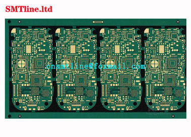
smd led circuit board
,electronic printed circuit board
-
BrandCNSMT
-
MODELElectronic Printed Circuit Board
-
Weight0.5KG
-
Lead TimeIN Stork
-
PackingBOX
-
CONditionWorking
-
POWER110V/220
-
PAYMENT TERMT/T, Paypal, Westernunion Are All Allowed
-
Place of Originchina
-
Brand Namecnsmt
-
CertificationCE
-
Model NumberSMD LED PCB Board
-
Minimum Order Quantity1
-
Pricenegotiation
-
Packaging Detailswoodenbox
-
Delivery Time5-7 work days
-
Payment TermsT/T, Western Union
-
Supply Ability10pcs/day
Professional Multilayer SMD LED PCB Board With Silk - Screen Printed
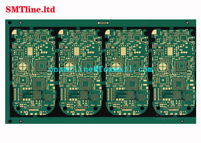

Professional Silk-screen Printed PCB Board Manufacturer 10 layer Multilayer PCB Board FR4 High TG Prototype board in qui
Quick Detail
Famous factory manufacture electronics washing machine PCBboard
PCB board Assembly board, print circuit board with electronic components
SMT/DIP PCB board OEM/ODM service, PS4 PCB board assembly
Advanced flash memory usb pcb board, Multilayer SMT / SMD PCBA printed circuit board PCB with design service
94v0 pcb board manufacturer PCB Assembly Factory, custom pcbmanufacturer with SMT DIP service
UL&RoHS LED PCB Manufacturer Professional PCB design,94V0 Aluminum Plate Samsung 5630 led smd pcb board
China Shenzhen OEM electronic Printed circuit board manufacturer,PCB board SMT assembly PCBA
Feature
| Product Name: | SMD LED PCB Board |
| Used for: | SMT FACTORY Electronic Circuit Board |
| Warranty: | 1 Year |
| Shipment | by air |
| Delivery Time: | 1-2Days |
| Our Main Market | Whole of the world |
Application
Converter editor
A high-speed analog-to-digital converter (ADC) is usually the most basic component of an analog front-end PCB circuit system. Since the performance of the analog/digital meta converter determines the overall performance of the system, system manufacturers often regard the analog/digital converter as the most important component. This article will explain in detail the operation principle of the front end of the ultrasound system, and specifically discuss the role of the analog/digital converter in it.
When PCB design the front-end PCB circuit of the ultrasound system, manufacturers must carefully consider several important factors in order to make proper trade-offs. Whether the medical staff can make the correct diagnosis depends on the critical role of the analog PCB circuit in this process.
The performance of an analog PCB circuit depends on many different parameters, including crosstalk between channels, spurious-free-signal dynamic range (SFDR), and total harmonic distortion. Therefore, manufacturers must consider these parameters in detail before deciding which analog PCB circuit to use.
Taking an analog/digital converter as an example, if an advanced PCB circuit such as a serial LVDS driver is added, the PCB circuit board can be reduced, and noise interference such as electromagnetic waves can be suppressed, which helps to further improve the PCB design of the system. The manufacture of miniaturized, high-performance and full-featured ultrasound system products has caused the market to continue to demand the production of low-power analog ICs with better integration with amplifiers, analog/digital converters, and small packages.
System Overview
The ultrasound imaging system is currently the most commonly used and most sophisticated signal processing instrument, and can assist medical personnel in making a correct diagnosis. At the front end of the ultrasound system, extremely precise analog signals are used to process PCB circuits such as analog/digital converters and low noise amplifiers (LNAs). The performance of these analog PCB circuits is a key factor in determining system performance.
Ultrasonic devices are very close to radar or sonar systems, but operate in different frequency bands (ranges). The radar operates in the GHz (gigahertz) range, sonar in the kHz (kHz) range, and the ultrasound system operates in the MHz (megahertz) range. The principle of these devices is almost the same as that of the array antenna radar system used in commercial and military aircraft. The PCB designers of radar systems use the principle of phased steering beamformer arrays, which were later adopted by the ultrasound system PCB designer and improved.
In all ultrasonic system instruments, there is a multiplex converter at the end of a relatively long cable (about 2 meters). The cable contains up to 256 micro-coaxial cables and is one of the most expensive components in an ultrasonic system. Ultrasound systems are generally equipped with a number of different transducer probes so that the medical staff responsible for the operation can select the appropriate transducer depending on the field requirements of the scanned image.
Image production
In the first step of the scanning process, each converter is responsible for generating a pulse signal and transmitting the signal. The transmitted pulse signal passes through the human body tissue in the form of high-frequency sound waves. The transmission speed of the sound waves is generally between 1 and 20 MHz. These pulse signals start timing and calibration detection in the human body. When the signal passes through the body tissue, some of the sound waves will be reflected back to the converter module, and the converter is responsible for detecting the potential of these echoes (after the converter sends the signal out, it will switch immediately and switch to receive mode). The strength of the echo signal depends on the position of the echo signal reflection point in the human body. The signal reflected directly from the subcutaneous tissue is generally very strong, and the signal reflected from the deep part of the human body is very weak.
Since health and safety laws are dictated by the maximum amount of radiation the human body can withstand, the electronic receiving system designed by the engineer PCB must be extremely sensitive. In the area of illness close to the human epidermis, we call it the near field, and the reflected energy is high. However, if the disease area is in a deep part of the human body, which is called the far field, the echo received will be extremely weak and must therefore be amplified 1000 times or more.
In the far-field image mode, its performance limit comes from all the noise present in the receiving link. The converter/cable assembly and the receiver system's low-noise amplifier are the two largest sources of extraneous noise. In the near-field video mode, the performance limitation comes from the size of the input signal. The ratio between these two signals determines the dynamic range of the ultrasonic instrument.
Through a series of receivers such as time phase conversion, amplitude adjustment, and intelligent cumulative echo energy, it is possible to obtain high-definition images. Using the time shift of the converter array and adjusting the amplitude of the received signal can make the device have the function of fixed-point observation of the scanning position. After serialized observations of different parts of the site, ultrasonic instruments can create a combined image.
Digital wave can complete the combination of signals. In a digital wave, echo pulse signals that are reflected from a point in the body are stored in each channel first, then arranged in order of priority, and fixed in a homonymous signal, and then gathered. This process of aggregating the outputs of multiple analog/digital converters can increase the gain because the noise within the channel is not related to each other. (Note: The analog wave-forming technique has basically become an outdated method, and most of the modern ones use digital wave-forming). The image is formed by sampling the simulation layer closest to the converter system, storing it, and digitizing them together.
The DBF system requires precise channel and channel matching. Both channels require VGA (video graphics array), and this will continue until the A/D converter device is large enough to handle the large dynamic range and can provide reasonable cost and low power consumption.
Image mode
1. Grayscale image -- produces basic black and white images
The image will be discriminated into units as small as 1mm, and the image will be rendered by emitting energy and detecting those returned energy (as previously described).
2. Doppler (Doppler) - Doppler mode is used to detect the velocity of objects moving in various environments by tracking the frequency offset of echoes. These principles are applied to examine the flow of blood or other fluids in the body. This technique is to launch a series of sound waves into the body and then perform a fast Fourier transform (FFT) on the reflected waves. This calculation and processing method can determine the signal frequency components from the human body and their relationship with the fluid velocity.
3. Vein and Arterial Patterns - This method is a combination of Doppler images and grayscale patterns. The rate and rhythm can be obtained by processing the audio signal generated by the Doppler shift.
Our products are sold all over the world, you can rest assured.